|
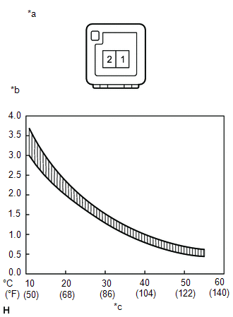
(a) Measure the resistance according to the value(s) in the table below.
Standard Resistance:
|
Tester Connection
|
Condition
|
Specified Condition
|
|
1 - 2
|
10°C (50°F)
|
3.00 to 3.73 kΩ
|
|
15°C (59°F)
|
2.45 to 2.88 kΩ
|
|
20°C (68°F)
|
1.95 to 2.30 kΩ
|
|
25°C (77°F)
|
1.60 to 1.80 kΩ
|
|
30°C (86°F)
|
1.28 to 1.47 kΩ
|
|
35°C (95°F)
|
1.00 to 1.22 kΩ
|
|
40°C (104°F)
|
0.80 to 1.00 kΩ
|
|
45°C (113°F)
|
0.65 to 0.85 kΩ
|
|
50°C (122°F)
|
0.50 to 0.70 kΩ
|
|
55°C (131°F)
|
0.44 to 0.60 kΩ
|
|
60°C (140°F)
|
0.36 to 0.50 kΩ
|
NOTICE:
- Touching the sensor even slightly may change the resistance value.
Hold the connector of the sensor.
- When measuring the resistance, the sensor temperature must be the
same as the ambient temperature.
HINT:
As the temperature increases, the resistance decreases (see the graph).
Text in Illustration
|
*a
|
Component without harness connected
(Cooler (Room Temperature Sensor) Thermistor)
|
|
*b
|
Resistance (kΩ)
|
|
*c
|
Temperature
|
If the result is not as specified, replace the cooler (room temperature
sensor) thermistor.
|