Components COMPONENTS ILLUSTRATION 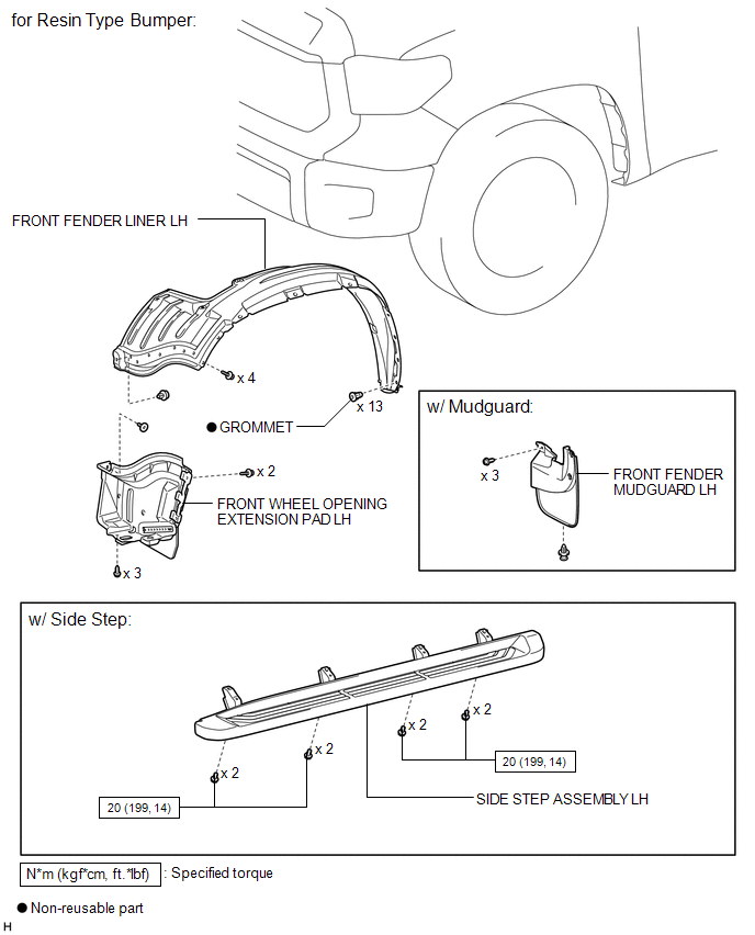
ILLUSTRATION 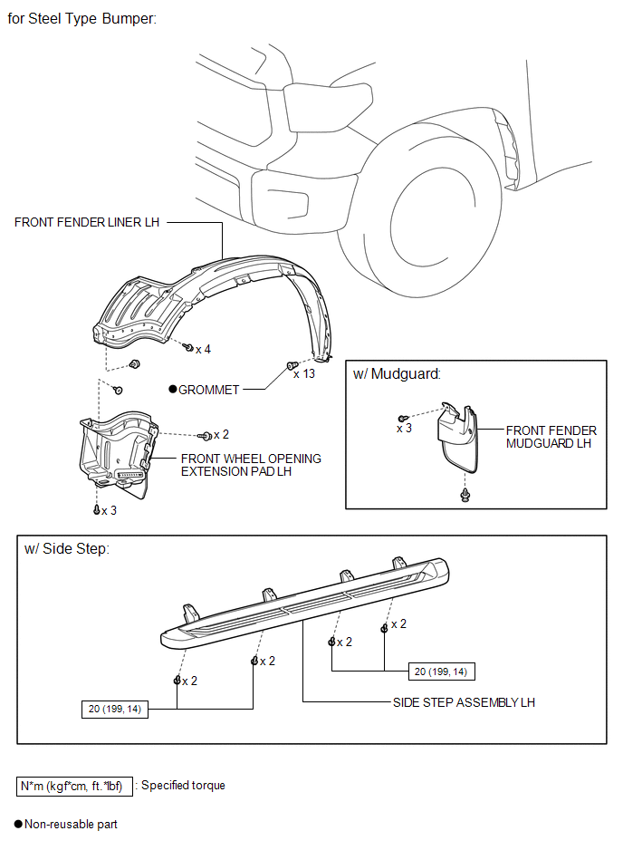
ILLUSTRATION 
ILLUSTRATION 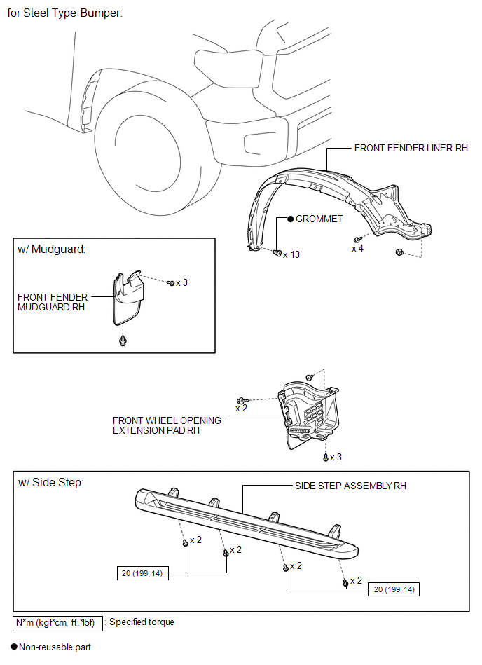
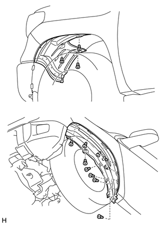
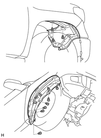
Installation INSTALLATION PROCEDURE 1. INSTALL FRONT WHEEL OPENING EXTENSION PAD LH (a) for Resin Type Bumper: (1) Install the front wheel opening extension pad LH with the 5 screws. (2) Install the clip. (b) for Steel Type Bumper: (1) Install the front wheel opening extension pad LH with the 3 screws. (2) Install the clip. (3) Install the 2 pin hold clips. 2. INSTALL FRONT FENDER LINER LH (a) Install the front fender liner LH with 13 new grommets. (b) Install the 4 screws and clip. 3. INSTALL FRONT WHEEL OPENING EXTENSION PAD RH (a) for Resin Type Bumper: (1) Install the front wheel opening extension pad RH with the 5 screws. (2) Install the clip. (b) for Steel Type Bumper: (1) Install the front wheel opening extension pad RH with the 3 screws. (2) Install the clip. (3) Install the 2 pin hold clips. 4. INSTALL FRONT FENDER LINER RH (a) Install the front fender liner RH with 13 new grommets. (b) Install the 4 screws and clip. 5. INSTALL FRONT FENDER MUDGUARD LH (w/ Mudguard)
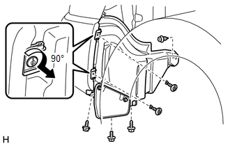
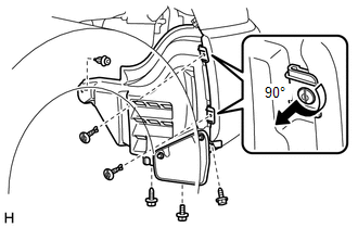
6. INSTALL FRONT FENDER MUDGUARD RH (w/ Mudguard) HINT: Use the same procedure described for the LH side. 7. INSTALL SIDE STEP ASSEMBLY LH (w/ Side Step)
8. INSTALL SIDE STEP ASSEMBLY RH (w/ Side Step) HINT: Use the same procedure described for the LH side. Removal REMOVAL PROCEDURE 1. REMOVE SIDE STEP ASSEMBLY LH (w/ Side Step)
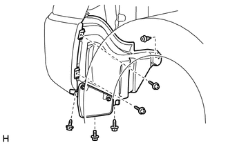
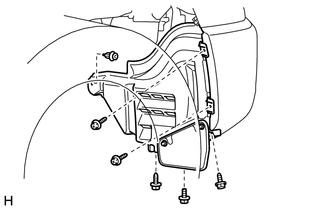
2. REMOVE SIDE STEP ASSEMBLY RH (w/ Side Step) HINT: Use the same procedure described for the LH side. 3. REMOVE FRONT FENDER MUDGUARD LH (w/ Mudguard)
4. REMOVE FRONT FENDER MUDGUARD RH (w/ Mudguard) HINT: Use the same procedure described for the LH side. 5. REMOVE FRONT FENDER LINER LH
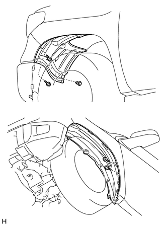
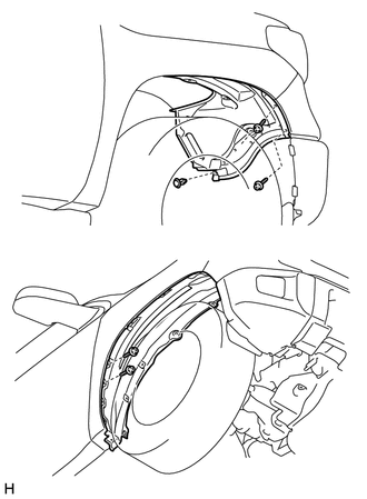
6. REMOVE FRONT WHEEL OPENING EXTENSION PAD LH
7. REMOVE FRONT FENDER LINER RH
8. REMOVE FRONT WHEEL OPENING EXTENSION PAD RH
|
Toyota Tundra Service Manual > Instrument Panel Safety Pad(for Floor Shift Type): Installation
INSTALLATION CAUTION / NOTICE / HINT HINT: A bolt without a torque specification is shown in the standard bolt chart (See page ). PROCEDURE 1. INSTALL NO. 1 INSTRUMENT PANEL CLIP 2. INSTALL NO. 3 INSTRUMENT PANEL STAY 3. INSTALL INSTRUMENT PANEL SUB-ASSEMBLY (a) Set the instrument panel sub-assembly ...