DESCRIPTION
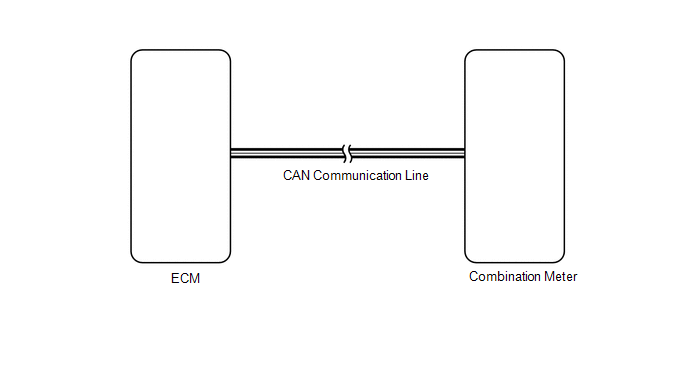
In this circuit, the combination meter receives the engine coolant temperature
signals from the ECM using the CAN communication lines. The combination meter displays
an engine coolant temperature that is calculated based on the data received from
the ECM.
WIRING DIAGRAM
PROCEDURE
|
1.
|
CHECK CAN COMMUNICATION SYSTEM
|
(a) Check if a CAN communication system DTC is output (See page
 ). ).
Result
|
Result
|
Proceed to
|
|
CAN communication system DTC is not output
|
A
|
|
CAN communication system DTC is output
|
B
|
| B |
 |
Go to CAN COMMUNICATION SYSTEM
|
| A |

|
|
|
2.
|
CHECK SFI SYSTEM (ENGINE COOLANT TEMPERATURE)
|
(a) Check if a SFI system DTC is output.
- for 1UR-FE (See page )
- for 3UR-FE (See page )
- for 3UR-FBE (See page )
Result
|
Result
|
Proceed to
|
|
SFI system DTC is not output
|
A
|
|
SFI system DTC (for 1UR-FE) is output
|
B
|
|
SFI system DTC (for 3UR-FE) is output
|
C
|
|
SFI system DTC (for 3UR-FBE) is output
|
D
|
| A |
|
REPLACE COMBINATION METER ASSEMBLY
|
| B |
|
Go to DIAGNOSTIC TROUBLE CODE CHART
|
| C |
|
Go to DIAGNOSTIC TROUBLE CODE CHART
|
| D |
|
Go to DIAGNOSTIC TROUBLE CODE CHART
|
| 

