DESCRIPTION
This DTC is stored when a power seat motor operates (a position control sensor
is being supplied with power) and the power supply voltage does not rise to the
specified value.
|
DTC Code
|
DTC Detection Condition
|
Trouble Area
|
|
B2658
|
A problem with the voltage supplied to the position control sensor.
|
- Position control ECU and switch assembly
- Front seat cushion frame sub-assembly LH
- Front seatback frame sub-assembly LH
- Harness or connector
|
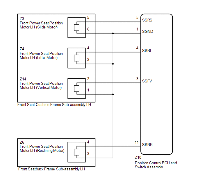
WIRING DIAGRAM
PROCEDURE
(a) Clear the DTCs (See page  ). ).
(b) Check for DTCs (See page ).
OK:
DTC B2658 is not output.
| OK |
 |
USE SIMULATION METHOD TO CHECK
|
| NG |

|
|
|
2.
|
CHECK HARNESS AND CONNECTOR (POSITION CONTROL ECU AND SWITCH ASSEMBLY
- FRONT SEAT CUSHION FRAME SUB-ASSEMBLY LH)
|
(a) Disconnect the Z10 position control ECU and switch assembly connector.
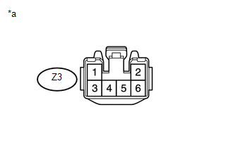
(b) Disconnect the Z3 front seat cushion frame sub-assembly LH (slide motor)
connector.
(c) Measure the resistance according to the value(s) in the table below.
Standard Resistance:
|
Tester Connection
|
Condition
|
Specified Condition
|
|
Z10-5 (SSRS) - Z3-5
|
Always
|
Below 1 Ω
|
|
Z10-1 (SGND) - Z3-6
|
Always
|
Below 1 Ω
|
|
Z10-5 (SSRS) - Z10-1 (SGND)
|
Always
|
10 kΩ or higher
|
|
Z10-5 (SSRS) or Z3-5 - Body ground
|
Always
|
10 kΩ or higher
|
|
Z10-1 (SGND) or Z3-6 - Body ground
|
Always
|
10 kΩ or higher
|
| NG |
|
REPAIR OR REPLACE HARNESS OR CONNECTOR
|
| OK |
|
|
|
|
3.
|
CHECK POSITION CONTROL ECU AND SWITCH ASSEMBLY (SLIDE MOTOR CIRCUIT)
|
|
(a) Reconnect the Z10 position control ECU and switch assembly connector.
|
|
(b) Measure the voltage according to the value(s) in the table below.
Standard Voltage:
|
Tester Connection
|
Switch Condition
|
Specified Condition
|
|
Z3-5 - Z3-6
|
Sliding switch on
|
4.8 to 5.1 V
|
Text in Illustration
|
*a
|
Front view of wire harness connector
(to Front Seat Cushion Frame Sub-assembly LH [Slide Motor])
|
| NG |
|
REPLACE POSITION CONTROL ECU AND SWITCH ASSEMBLY
|
| OK |
|
|
|
|
4.
|
CHECK HARNESS AND CONNECTOR (POSITION CONTROL ECU AND SWITCH ASSEMBLY
- FRONT SEAT CUSHION FRAME SUB-ASSEMBLY LH)
|
(a) Disconnect the Z10 position control ECU and switch assembly connector.
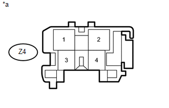
(b) Disconnect the Z4 front seat cushion frame sub-assembly LH (lifter motor)
connector.
(c) Measure the resistance according to the value(s) in the table below.
Standard Resistance:
|
Tester Connection
|
Condition
|
Specified Condition
|
|
Z10-4 (SSRL) - Z4-4
|
Always
|
Below 1 Ω
|
|
Z10-1 (SGND) - Z4-3
|
Always
|
Below 1 Ω
|
|
Z10-4 (SSRL) - Z10-1 (SGND)
|
Always
|
10 kΩ or higher
|
|
Z10-4 (SSRL) or Z4-4 - Body ground
|
Always
|
10 kΩ or higher
|
|
Z10-1 (SGND) or Z4-3 - Body ground
|
Always
|
10 kΩ or higher
|
| NG |
|
REPAIR OR REPLACE HARNESS OR CONNECTOR
|
| OK |
|
|
|
|
5.
|
CHECK POSITION CONTROL ECU AND SWITCH ASSEMBLY (LIFTER MOTOR CIRCUIT)
|
|
(a) Reconnect the Z10 position control ECU and switch assembly connector.
|
|
(b) Measure the voltage according to the value(s) in the table below.
Standard Voltage:
|
Tester Connection
|
Switch Condition
|
Specified Condition
|
|
Z4-4 - Z4-3
|
Lifter switch on
|
4.8 to 5.1 V
|
Text in Illustration
|
*a
|
Front view of wire harness connector
(to Front Seat Cushion Frame Sub-assembly LH [Lifter Motor])
|
| NG |
|
REPLACE POSITION CONTROL ECU AND SWITCH ASSEMBLY
|
| OK |
|
|
|
|
6.
|
CHECK HARNESS AND CONNECTOR (POSITION CONTROL ECU AND SWITCH ASSEMBLY
- FRONT SEAT CUSHION FRAME SUB-ASSEMBLY LH)
|
(a) Disconnect the Z10 position control ECU and switch assembly connector.
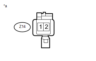
(b) Disconnect the Z14 front seat cushion frame sub-assembly LH (vertical motor)
connector.
(c) Measure the resistance according to the value(s) in the table below.
Standard Resistance:
|
Tester Connection
|
Condition
|
Specified Condition
|
|
Z10-3 (SSFV) - Z14-2
|
Always
|
Below 1 Ω
|
|
Z10-1 (SGND) - Z14-1
|
Always
|
Below 1 Ω
|
|
Z10-3 (SSFV) - Z10-1 (SGND)
|
Always
|
10 kΩ or higher
|
|
Z10-3 (SSFV) or Z14-2 - Body ground
|
Always
|
10 kΩ or higher
|
|
Z10-1 (SGND) or Z14-1 - Body ground
|
Always
|
10 kΩ or higher
|
| NG |
|
REPAIR OR REPLACE HARNESS OR CONNECTOR
|
| OK |
|
|
|
|
7.
|
CHECK POSITION CONTROL ECU AND SWITCH ASSEMBLY (VERTICAL MOTOR CIRCUIT)
|
|
(a) Reconnect the Z10 position control ECU and switch assembly connector.
|
|
(b) Measure the voltage according to the value(s) in the table below.
Standard Voltage:
|
Tester Connection
|
Switch Condition
|
Specified Condition
|
|
Z14-2 - Z14-1
|
Front vertical switch on
|
4.8 to 5.1 V
|
Text in Illustration
|
*a
|
Front view of wire harness connector
(to Front Seat Cushion Frame Sub-assembly LH [Vertical Motor])
|
| NG |
|
REPLACE POSITION CONTROL ECU AND SWITCH ASSEMBLY
|
| OK |
|
|
|
|
8.
|
CHECK FRONT SEAT CUSHION FRAME SUB-ASSEMBLY LH
|
(a) Temporarily replace the front seat cushion frame sub-assembly LH with a new
or normally functioning one (See page ).
(b) Clear the DTCs (See page ).
(c) Check for DTCs (See page ).
OK:
DTC B2658 is not output.
| OK |
|
END (FRONT SEAT CUSHION FRAME SUB-ASSEMBLY LH WAS DEFECTIVE)
|
| NG |
|
|
|
|
9.
|
CHECK HARNESS AND CONNECTOR (POSITION CONTROL ECU AND SWITCH ASSEMBLY
- FRONT SEATBACK FRAME SUB-ASSEMBLY LH)
|
(a) Disconnect the Z10 position control ECU and switch assembly connector.
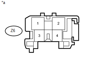
(b) Disconnect the Z6 front seatback frame sub-assembly LH (reclining motor)
connector.
(c) Measure the resistance according to the value(s) in the table below.
Standard Resistance:
|
Tester Connection
|
Condition
|
Specified Condition
|
|
Z10-11 (SSRR) - Z6-4
|
Always
|
Below 1 Ω
|
|
Z10-1 (SGND) - Z6-3
|
Always
|
Below 1 Ω
|
|
Z10-11 (SSRR) - Z10-1 (SGND)
|
Always
|
10 kΩ or higher
|
|
Z10-11 (SSRR) or Z6-4 - Body ground
|
Always
|
10 kΩ or higher
|
|
Z10-1 (SGND) or Z6-3 - Body ground
|
Always
|
10 kΩ or higher
|
| NG |
|
REPAIR OR REPLACE HARNESS OR CONNECTOR
|
| OK |
|
|
|
|
10.
|
CHECK POSITION CONTROL ECU AND SWITCH ASSEMBLY (RECLINING MOTOR CIRCUIT)
|
|
(a) Reconnect the Z10 position control ECU and switch assembly connector.
|
|
(b) Measure the voltage according to the value(s) in the table below.
Standard Voltage:
|
Tester Connection
|
Switch Condition
|
Specified Condition
|
|
Z6-4 - Z6-3
|
Reclining switch on
|
4.8 to 5.1 V
|
Text in Illustration
|
*a
|
Front view of wire harness connector
(to Front Seatback Frame Sub-assembly LH [Reclining Motor])
|
| NG |
|
REPLACE POSITION CONTROL ECU AND SWITCH ASSEMBLY
|
| OK |
|
|
|
|
11.
|
CHECK FRONT SEATBACK FRAME SUB-ASSEMBLY LH
|
(a) Temporarily replace the front seatback frame sub-assembly LH (reclining motor)
with a new or normally functioning one (See page
).
(b) Clear the DTCs (See page ).
(c) Check for DTCs (See page ).
OK:
DTC B2658 is not output.
| OK |
|
END (FRONT SEATBACK FRAME SUB-ASSEMBLY LH WAS DEFECTIVE)
|
| NG |
|
REPLACE POSITION CONTROL ECU AND SWITCH ASSEMBLY
|
|