DESCRIPTION
When a signal is input into the position control ECU and switch assembly, the
ECU manages the signals received from the power seat switches, and operates each
motors. If the position control ECU and switch assembly receives more than 2 motor
operation signals, the motor is stopped. Manual operation is restarted after the
position control ECU and switch assembly receives 1 signal only.
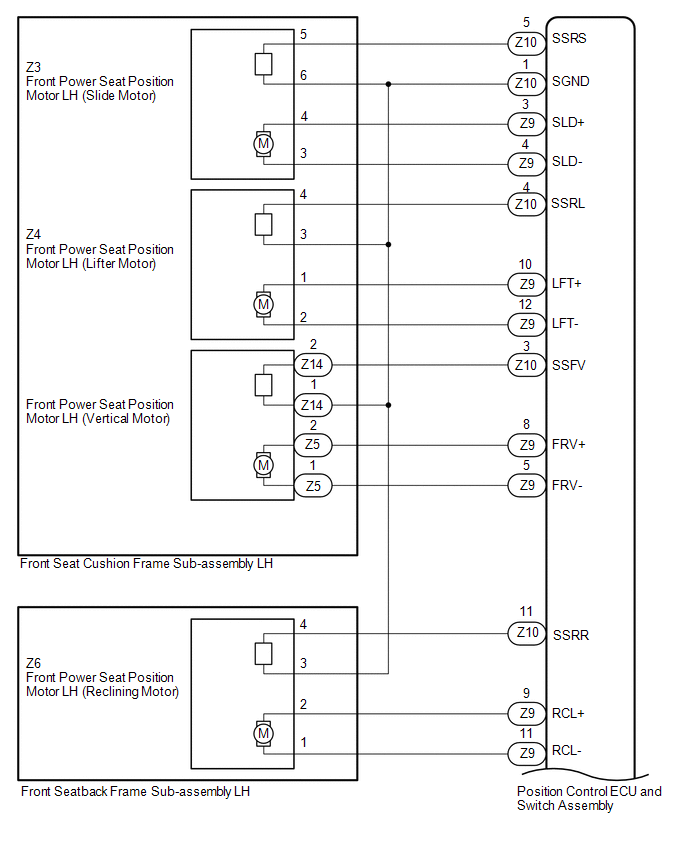
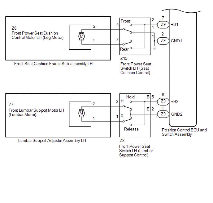
WIRING DIAGRAM
PROCEDURE
|
1.
|
CHECK FRONT POWER SEAT OPERATION
|
(a) Check which power seat functions are malfunctioning.
Result
|
Result
|
Proceed to
|
|
One or more power seat functions do not operate
|
A
|
|
All power seat functions do not operate
|
B
|
| B |
 |
GO to OTHER FLOW CHART (Front Power Seat does not Operate with Front
Power Seat Switch)
|
| A |

|
|
|
2.
|
CHECK FRONT POWER SEAT OPERATION
|
(a) Check that each function of the power seat operates normally by using the
power seat switches (See page  ). ).
Result
|
Result
|
Proceed to
|
|
Slide, front vertical and lifter functions do not operate
|
A
|
|
Reclining functions do not operate
|
B
|
|
Lumbar support adjustment function does not operate
|
C
|
|
Leg support function does not operate
|
D
|
| B |
|
GO TO STEP 7
|
| C |
|
GO TO STEP 11
|
| D |
|
GO TO STEP 15
|
| A |
|
|
|
|
3.
|
READ VALUE USING TECHSTREAM (SLIDE, LIFTER, FRONT VERTICAL)
|
(a) Connect the Techstream to the DLC3.
(b) Turn the ignition switch to ON.
(c) Turn the Techstream on.
(d) Enter the following menus: Body Electrical / Driver Seat / Data List.
(e) Read the Data List according to the display on the Techstream.
Driver Seat
|
Tester Display
|
Measurement item/Range
|
Normal Condition
|
Diagnostic Note
|
|
Front Vertical Down
|
Front vertical switch signal (Downward) / ON or OFF
|
ON: Front vertical switch (Downward) on
OFF: Front vertical switch (Downward) off
|
-
|
|
Front Vertical Up
|
Front vertical switch signal (Upward) / ON or OFF
|
ON: Front vertical switch (Upward) on
OFF: Front vertical switch (Upward) off
|
-
|
|
Lifter Switch Down
|
Lifter switch signal (Downward) / ON or OFF
|
ON: Lifter switch (Downward) on
OFF: Lifter switch (Downward) off
|
-
|
|
Lifter Switch Up
|
Lifter switch signal (Upward) / ON or OFF
|
ON: Lifter switch (Upward) on
OFF: Lifter switch (Upward) off
|
-
|
|
Slide Rear
|
Sliding switch signal (Rearward) / ON or OFF
|
ON: Sliding switch (Rearward) on
OFF: Sliding switch (Rearward) off
|
-
|
|
Slide Front
|
Sliding switch signal (Forward) / ON or OFF
|
ON: Sliding switch (Forward) on
OFF: Sliding switch (Forward) off
|
-
|
OK:
ON or OFF is displayed on the Techstream according to the table above.
| NG |
|
REPLACE POSITION CONTROL ECU AND SWITCH ASSEMBLY
|
| OK |
|
|
|
|
4.
|
INSPECT FRONT SEAT CUSHION FRAME SUB-ASSEMBLY LH (SLIDE, LIFTER, VERTICAL
MOTOR)
|
(a) Check the operation of the slide motor.
(1) Remove the front seat cushion frame sub-assembly LH (slide motor) (See page
).
(2) Inspect the front seat cushion frame sub-assembly LH (slide motor) (See page
).
(b) Check the operation of the lifter motor.
(1) Remove the front seat cushion frame sub-assembly LH (lifter motor) (See page
).
(2) Inspect the front seat cushion frame sub-assembly LH (lifter motor) (See
page ).
(c) Check the operation of the vertical motor.
(1) Remove the front seat cushion frame sub-assembly LH (vertical motor) (See
page ).
(2) Inspect the front seat cushion frame sub-assembly LH (vertical motor) (See
page ).
| NG |
|
REPLACE FRONT SEAT CUSHION FRAME SUB-ASSEMBLY LH
|
| OK |
|
|
|
|
5.
|
CHECK HARNESS AND CONNECTOR (POSITION CONTROL ECU AND SWITCH ASSEMBLY
- FRONT SEAT CUSHION FRAME SUB-ASSEMBLY LH)
|
(a) Disconnect the Z9 and Z10 position control ECU and switch assembly connectors.
(b) Measure the resistance according to the value(s) in the table below.
Standard Resistance:
|
Tester Connection
|
Condition
|
Specified Condition
|
|
Z10-5 (SSRS) - Z3-5
|
Always
|
Below 1 Ω
|
|
Z9-3 (SLD+) - Z3-4
|
Always
|
Below 1 Ω
|
|
Z9-4 (SLD-) - Z3-3
|
Always
|
Below 1 Ω
|
|
Z10-1 (SGND) - Z3-6
|
Always
|
Below 1 Ω
|
|
Z10-3 (SSFV) - Z14-2
|
Always
|
Below 1 Ω
|
|
Z9-8 (FRV+) - Z5-2
|
Always
|
Below 1 Ω
|
|
Z9-5 (FRV-) - Z5-1
|
Always
|
Below 1 Ω
|
|
Z10-1 (SGND) - Z14-1
|
Always
|
Below 1 Ω
|
|
Z10-4 (SSRL) - Z4-4
|
Always
|
Below 1 Ω
|
|
Z9-10 (LFT+) - Z4-1
|
Always
|
Below 1 Ω
|
|
Z9-12 (LFT-) - Z4-2
|
Always
|
Below 1 Ω
|
|
Z10-1 (SGND) - Z4-3
|
Always
|
Below 1 Ω
|
|
Z10-5 (SSRS) or Z3-5 - Body ground
|
Always
|
10 kΩ or higher
|
|
Z9-3 (SLD+) or Z3-4 - Body ground
|
Always
|
10 kΩ or higher
|
|
Z9-4 (SLD-) or Z3-3 - Body ground
|
Always
|
10 kΩ or higher
|
|
Z10-1 (SGND) or Z3-6 - Body ground
|
Always
|
10 kΩ or higher
|
|
Z10-1 (SGND) or Z14-1 - Body ground
|
Always
|
10 kΩ or higher
|
|
Z10-1 (SGND) or Z4-3 - Body ground
|
Always
|
10 kΩ or higher
|
|
Z10-3 (SSFV) or Z14-2 - Body ground
|
Always
|
10 kΩ or higher
|
|
Z9-8 (FRV+) or Z5-2 - Body ground
|
Always
|
10 kΩ or higher
|
|
Z9-5 (FRV-) or Z5-1 - Body ground
|
Always
|
10 kΩ or higher
|
|
Z10-4 (SSRL) or Z4-4 - Body ground
|
Always
|
10 kΩ or higher
|
|
Z9-10 (LFT+) or Z4-1 - Body ground
|
Always
|
10 kΩ or higher
|
|
Z9-12 (LFT-) or Z4-2 - Body ground
|
Always
|
10 kΩ or higher
|
| NG |
|
REPAIR OR REPLACE HARNESS OR CONNECTOR
|
| OK |
|
|
|
|
6.
|
CHECK POSITION CONTROL ECU AND SWITCH ASSEMBLY
|
(a) Temporarily replace the position control ECU and switch assembly with a new
or normally functioning one (See page ).
(b) Check the front power seat control system (See page
).
OK:
Power seat operates normally.
| OK |
|
END (POSITION CONTROL ECU AND SWITCH ASSEMBLY WAS DEFECTIVE)
|
| NG |
|
REPLACE FRONT SEAT CUSHION FRAME SUB-ASSEMBLY LH
|
|
7.
|
READ VALUE USING TECHSTREAM (RECLINING)
|
(a) Connect the Techstream to the DLC3.
(b) Turn the ignition switch to ON.
(c) Turn the Techstream on.
(d) Enter the following menus: Body Electrical / Driver Seat / Data List.
(e) Read the Data List according to the display on the Techstream.
Driver Seat
|
Tester Display
|
Measurement item/Range
|
Normal Condition
|
Diagnostic Note
|
|
Reclining Rear
|
Reclining switch signal (Rearward) / ON or OFF
|
ON: Reclining switch (Rearward) on
OFF: Reclining switch (Rearward) off
|
-
|
|
Reclining Front
|
Reclining switch signal (Forward) / ON or OFF
|
ON: Reclining switch (Forward) on
OFF: Reclining switch (Forward) off
|
-
|
OK:
ON or OFF is displayed on the Techstream according to the table above.
| NG |
|
REPLACE POSITION CONTROL ECU AND SWITCH ASSEMBLY
|
| OK |
|
|
|
|
8.
|
INSPECT FRONT SEATBACK FRAME SUB-ASSEMBLY LH (RECLINING MOTOR)
|
(a) Check the operation of the reclining motor.
(1) Remove the front seatback frame sub-assembly LH (reclining motor) (See page
).
(2) Inspect the front seatback frame sub-assembly LH (reclining motor) (See page
).
| NG |
|
REPLACE FRONT SEATBACK FRAME SUB-ASSEMBLY LH
|
| OK |
|
|
|
|
9.
|
CHECK HARNESS AND CONNECTOR (POSITION CONTROL ECU AND SWITCH ASSEMBLY
- FRONT SEATBACK FRAME SUB-ASSEMBLY LH)
|
(a) Disconnect the Z9 and Z10 position control ECU and switch assembly connectors.
(b) Measure the resistance according to the value(s) in the table below.
Standard Resistance:
|
Tester Connection
|
Condition
|
Specified Condition
|
|
Z10-11 (SSRR) - Z6-4
|
Always
|
Below 1 Ω
|
|
Z9-9 (RCL+) - Z6-2
|
Always
|
Below 1 Ω
|
|
Z9-11 (RCL-) - Z6-1
|
Always
|
Below 1 Ω
|
|
Z10-1 (SGND) - Z6-3
|
Always
|
Below 1 Ω
|
|
Z10-11 (SSRR) or Z6-4 - Body ground
|
Always
|
10 kΩ or higher
|
|
Z9-9 (RCL+) or Z6-2 - Body ground
|
Always
|
10 kΩ or higher
|
|
Z9-11 (RCL-) or Z6-1 - Body ground
|
Always
|
10 kΩ or higher
|
|
Z10-1 (SGND) or Z6-3 - Body ground
|
Always
|
10 kΩ or higher
|
| NG |
|
REPAIR OR REPLACE HARNESS OR CONNECTOR
|
| OK |
|
|
|
|
10.
|
CHECK POSITION CONTROL ECU AND SWITCH ASSEMBLY
|
(a) Temporarily replace the position control ECU and switch assembly with a new
or normally functioning one (See page ).
(b) Check the front power seat control system (See page
).
OK:
Power seat operates normally
| OK |
|
END (POSITION CONTROL ECU AND SWITCH ASSEMBLY WAS DEFECTIVE)
|
| NG |
|
REPLACE FRONT SEATBACK FRAME SUB-ASSEMBLY LH
|
|
11.
|
INSPECT LUMBAR SUPPORT ADJUSTER ASSEMBLY LH (LUMBAR MOTOR)
|
(a) Check the operation of the lumbar motor.
(1) Remove the lumbar support adjuster assembly LH (lumbar motor) (See page
).
(2) Inspect the lumbar support adjuster assembly LH (lumbar motor) (See page
).
| NG |
|
REPLACE LUMBAR SUPPORT ADJUSTER ASSEMBLY LH (LUMBAR MOTOR)
|
| OK |
|
|
|
|
12.
|
INSPECT FRONT POWER SEAT SWITCH LH (LUMBAR SUPPORT CONTROL)
|
(a) Check the operation of the lumbar support control.
(1) Remove the front power seat switch LH (lumbar support control) (See page
).
(2) Inspect the front power seat switch LH (lumbar support control) (See page
).
| NG |
|
REPLACE FRONT POWER SEAT SWITCH LH
|
| OK |
|
|
|
|
13.
|
CHECK HARNESS AND CONNECTOR (POSITION CONTROL ECU AND SWITCH ASSEMBLY
- FRONT POWER SEAT SWITCH LH)
|
(a) Disconnect the Z9 position control ECU and switch assembly connector.
(b) Measure the resistance according to the value(s) in the table below.
Standard Resistance:
|
Tester Connection
|
Condition
|
Specified Condition
|
|
Z9-6 (+B2) - Z2-5 (B)
|
Always
|
Below 1 Ω
|
|
Z9-1 (GND2) - Z2-2 (E)
|
Always
|
Below 1 Ω
|
|
Z9-6 (+B2) or Z2-5 (B) - Body ground
|
Always
|
10 kΩ or higher
|
|
Z9-1 (GND2) or Z2-2 (E) - Body ground
|
Always
|
10 kΩ or higher
|
| NG |
|
REPAIR OR REPLACE HARNESS OR CONNECTOR
|
| OK |
|
|
|
|
14.
|
CHECK HARNESS AND CONNECTOR (LUMBAR SUPPORT ADJUSTER ASSEMBLY LH - FRONT
POWER SEAT SWITCH LH)
|
(a) Disconnect the Z7 lumbar support adjuster assembly LH (lumbar motor) connector.
(b) Measure the resistance according to the value(s) in the table below.
Standard Resistance:
|
Tester Connection
|
Condition
|
Specified Condition
|
|
Z2-1 (R) - Z7-1
|
Always
|
Below 1 Ω
|
|
Z2-3 (H) - Z7-2
|
Always
|
Below 1 Ω
|
|
Z2-1 (R) or Z7-1 - Body ground
|
Always
|
10 kΩ or higher
|
|
Z2-3 (H) or Z7-2 - Body ground
|
Always
|
10 kΩ or higher
|
| OK |
|
REPLACE POSITION CONTROL ECU AND SWITCH ASSEMBLY
|
| NG |
|
REPAIR OR REPLACE HARNESS OR CONNECTOR
|
|
15.
|
INSPECT FRONT SEAT CUSHION FRAME SUB-ASSEMBLY LH (LEG MOTOR)
|
(a) Check the operation of the leg motor.
(1) Remove the front seat cushion frame sub-assembly LH (leg motor) (See page
).
(2) Inspect the front seat cushion frame sub-assembly LH (leg motor) )(See page
).
| NG |
|
REPLACE FRONT SEAT CUSHION FRAME SUB-ASSEMBLY LH
|
| OK |
|
|
|
|
16.
|
INSPECT FRONT POWER SEAT SWITCH LH (SEAT CUSHION CONTROL)
|
(a) Check the operation of the seat cushion control.
(1) Remove the front power seat switch LH (seat cushion control) (See page
).
(2) Inspect the front power seat switch LH (seat cushion control) (See page
).
| NG |
|
REPLACE FRONT POWER SEAT SWITCH LH
|
| OK |
|
|
|
|
17.
|
CHECK HARNESS AND CONNECTOR (POSITION CONTROL ECU AND SWITCH ASSEMBLY
- FRONT POWER SEAT SWITCH LH)
|
(a) Disconnect the Z9 position control ECU and switch assembly connector.
(b) Measure the resistance according to the value(s) in the table below.
Standard Resistance:
|
Tester Connection
|
Condition
|
Specified Condition
|
|
Z9-7 (+B1) - Z15-2
|
Always
|
Below 1 Ω
|
|
Z9-2 (GND1) - Z15-1
|
Always
|
Below 1 Ω
|
|
Z9-2 (GND1) - Z15-4
|
Always
|
Below 1 Ω
|
|
Z9-7 (+B1) or Z15-2 - Body ground
|
Always
|
10 kΩ or higher
|
|
Z9-2 (GND1) or Z15-1 - Body ground
|
Always
|
Below 1 Ω
|
|
Z9-2 (GND1) or Z15-4 - Body ground
|
Always
|
Below 1 Ω
|
| NG |
|
REPAIR OR REPLACE HARNESS OR CONNECTOR
|
| OK |
|
|
|
|
18.
|
CHECK HARNESS AND CONNECTOR (FRONT SEAT CUSHION FRAME SUB-ASSEMBLY LH
- FRONT POWER SEAT SWITCH LH)
|
(a) Disconnect the Z8 front seat cushion frame sub-assembly LH (leg motor) connector.
(b) Measure the resistance according to the value(s) in the table below.
Standard Resistance:
|
Tester Connection
|
Condition
|
Specified Condition
|
|
Z15-5 - Z8-2
|
Always
|
Below 1 Ω
|
|
Z15-3 - Z8-1
|
Always
|
Below 1 Ω
|
|
Z15-5 or Z8-2 - Body ground
|
Always
|
10 kΩ or higher
|
|
Z15-3 or Z8-1 - Body ground
|
Always
|
10 kΩ or higher
|
| OK |
|
REPLACE POSITION CONTROL ECU AND SWITCH ASSEMBLY
|
| NG |
|
REPAIR OR REPLACE HARNESS OR CONNECTOR
|
| 

