DESCRIPTION The occupant classification system circuit consists of the airbag sensor assembly and the occupant classification system. If the airbag sensor assembly receives signals from the occupant classification ECU, it determines whether the front passenger airbag, the front seat airbag RH and front seat outer belt should be operated. DTC B1650 is stored when a malfunction is detected in the occupant classification system circuit.
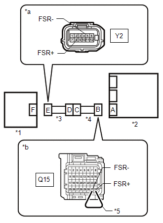
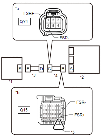
WIRING DIAGRAM 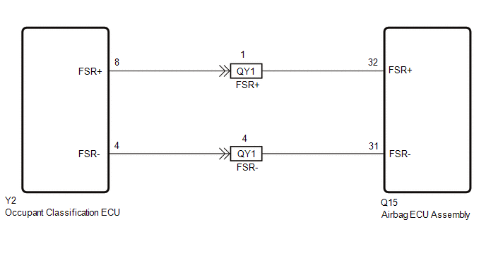
CAUTION / NOTICE / HINT NOTICE:
PROCEDURE
(a) Check for occupant classification system DTCs. Click here OK: DTCs are not output.
(a) Turn the ignition switch off. (b) Disconnect the cable from the negative (-) battery terminal, and wait for at least 90 seconds. (c) Check that the connectors are properly connected to the airbag sensor assembly and occupant classification ECU. OK: The connectors are properly connected.
(a) Disconnect the connectors from the airbag sensor assembly and occupant classification ECU.
(b) Turn the ignition switch to ON. (c) Measure the voltage according to the value(s) in the table below. Standard Voltage:
(d) Turn the ignition switch off. (e) Disconnect the cable from the negative (-) battery terminal, and wait for at least 90 seconds. (f) Using a service wire, connect terminals 32 (FSR+) and 31 (FSR-) of connector B. NOTICE: Do not forcibly insert the service wire into the terminals of the connector when connecting a service wire. (g) Measure the resistance according to the value(s) in the table below. Standard Resistance:
(h) Disconnect the service wire from connector B. (i) Measure the resistance according to the value(s) in the table below. Standard Resistance:
(b) Connect the cable to the negative (-) battery terminal, and wait for at least 2 seconds. (c) Turn the ignition switch to ON. (d) Measure the voltage according to the value(s) in the table below. Standard Voltage:
(e) Turn the ignition switch off. (f) Disconnect the cable from the negative (-) battery terminal, and wait for at least 90 seconds. (g) Using a service wire, connect terminals 32 (FSR+) and 31 (FSR-) of connector B. NOTICE: Do not forcibly insert the service wire into the terminals of the connector when connecting a service wire. (h) Measure the resistance according to the value(s) in the table below. Standard Resistance:
(i) Disconnect the service wire from connector B. (j) Measure the resistance according to the value(s) in the table below. Standard Resistance:
|
Toyota Tundra Service Manual > Key Reminder Warning System: How To Proceed With Troubleshooting
CAUTION / NOTICE / HINT HINT: Use the following procedures to troubleshoot the key reminder warning system. *: Use the Techstream. PROCEDURE 1. VEHICLE BROUGHT TO WORKSHOP NEXT 2. INSPECT BATTERY VOLTAGE Standard Voltage: 11 to 14 V If the voltage is below 11 V, recharge or replace the battery befor ...