DESCRIPTION The seat position airbag sensor circuit consists of the airbag sensor assembly and seat position airbag sensor. DTC B1653 is stored when a malfunction is detected in the seat position airbag sensor circuit.
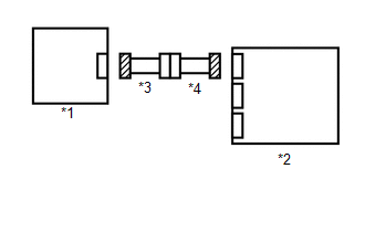
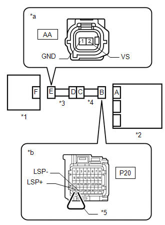
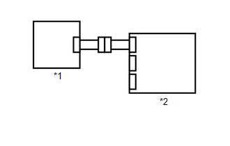
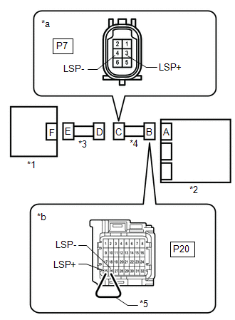
WIRING DIAGRAM 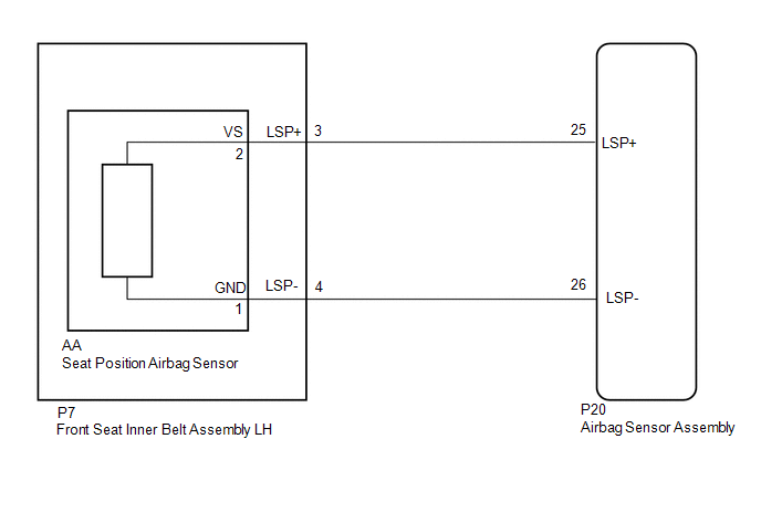
CAUTION / NOTICE / HINT NOTICE:
PROCEDURE
(a) Turn the ignition switch off. (b) Disconnect the cable from the negative (-) battery terminal, and wait for at least 90 seconds. (c) Check that the connectors are properly connected to the airbag sensor assembly and seat position airbag sensor. OK: Connectors are properly connected.
(b) Check that the connectors (on the airbag sensor assembly side and seat position airbag sensor side) are not damaged. OK: Connectors are not deformed or damaged.
(b) Turn the ignition switch to ON. (c) Measure the voltage according to the value(s) in the table below. Standard Voltage:
(d) Turn the ignition switch off. (e) Disconnect the cable from the negative (-) battery terminal, and wait for at least 90 seconds. (f) Using a service wire, connect terminals 26 (LSP-) and 25 (LSP+) of connector B. NOTICE: Do not forcibly insert the service wire into the terminals of the connector when connecting a service wire. (g) Measure the resistance according to the value(s) in the table below. Standard Resistance:
(h) Disconnect the service wire from connector B. (i) Measure the resistance according to the value(s) in the table below. Standard Resistance:
(b) Connect the cable to the negative (-) battery terminal, and wait for at least 2 seconds. (c) Turn the ignition switch to ON, and wait for at least 60 seconds. (d) Clear the DTCs. Click here (e) Turn the ignition switch off. (f) Turn the ignition switch to ON, and wait for at least 60 seconds. (g) Check for DTCs. Click here
HINT: Codes other than DTC B1653 may be output at this time, but they are not related to this check.
(a) Turn the ignition switch off. (b) Disconnect the cable from the negative (-) battery terminal, and wait for at least 90 seconds. (c) Replace the seat position airbag sensor. Click here HINT: Perform the inspection using parts from a normal vehicle if possible.
(b) Turn the ignition switch to ON, and wait for at least 60 seconds. (c) Clear the DTCs. Click here (d) Turn the ignition switch off. (e) Turn the ignition switch to ON, and wait for at least 60 seconds. (f) Check for DTCs. Click here
HINT: Codes other than DTC B1653 may be output at this time, but they are not related to this check.
(b) Connect the cable to the negative (-) battery terminal, and wait for at least 2 seconds. (c) Turn the ignition switch to ON. (d) Measure the voltage according to the value(s) in the table below. Standard Voltage:
(e) Turn the ignition switch off. (f) Disconnect the cable from the negative (-) battery terminal, and wait for at least 90 seconds. (g) Using a service wire, connect terminals 26 (LSP-) and 25 (LSP+) of connector B. NOTICE: Do not forcibly insert the service wire into the terminals of the connector when connecting a service wire. (h) Measure the resistance according to the value(s) in the table below. Standard Resistance:
(i) Disconnect the service wire from connector B. (j) Measure the resistance according to the value(s) in the table below. Standard Resistance:
|
Toyota Tundra Service Manual > Power Door Lock Control System: System Description
SYSTEM DESCRIPTION 1. POWER DOOR LOCK CONTROL SYSTEM DESCRIPTION (a) The power door lock control system locks/unlocks all the doors. The power window regulator master switch assembly (door control switch assembly LH) and the door control switch assembly RH on the front passenger door send "lock ...