DISPOSAL CAUTION / NOTICE / HINT CAUTION: Before performing pre-disposal deployment of any SRS component, review and closely follow all applicable environmental and hazardous material regulations. Pre-disposal deployment may be considered hazardous material treatment. PROCEDURE 1. PRECAUTION CAUTION:
HINT: When scrapping a vehicle equipped with the SRS or disposing of the curtain shield airbag assembly, be sure to deploy the airbag first in accordance with the procedure described below. If any abnormality occurs with the airbag deployment, contact the SERVICE DEPT. of TOYOTA MOTOR SALES, U.S.A., INC. 2. DISPOSE OF CURTAIN SHIELD AIRBAG ASSEMBLY (WHEN INSTALLED IN VEHICLE) HINT: Prepare a battery as the power source to deploy the airbag.
(b) Read the precaution (see page (c) Disconnect the cable from the negative (-) battery terminal. CAUTION: Wait at least 90 seconds after disconnecting the cable from the negative (-) battery terminal to prevent airbag and seat belt pretensioner activation. (d) Remove the roof headlining (for CrewMax) (see page
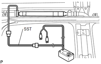
(e) Install SST. 
(1) Disconnect the connector from the curtain shield airbag. NOTICE: When handling the airbag connector, take care not to damage the airbag wire harness. (2) After connecting SST each other, connect them to the curtain shield airbag. SST: 09082-00700 SST: 09082-00802 09082-10801 09082-40800 NOTICE: To avoid damaging SST connector and wire harness, do not lock the secondary lock of the twin lock.
(4) Maintaining enough clearance for SST wire harness in the rear side window, close all doors and windows of the vehicle. NOTICE: Take care not to damage SST wire harness. (5) Connect the red clip of SST to the battery positive (+) terminal and black clip of SST to the battery negative (-) terminal. (f) Deploy the airbag. (1) Check that no one is inside the vehicle or within a 10 m (32.8 ft.) radius of the vehicle. (2) Press SST activation switch and deploy the airbag. CAUTION:
HINT: The airbag is deployed as the LED of SST activation switch comes on. 3. DISPOSE OF CURTAIN SHIELD AIRBAG ASSEMBLY (WHEN NOT INSTALLED IN VEHICLE) CAUTION: Be sure to follow the procedure detailed below when deploying the airbag. HINT: Prepare a battery as the power source to deploy the airbag.
(b) Remove the curtain shield airbag (see page
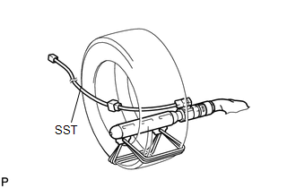
(d) Using a service-purpose wire harness for the vehicle, tie down the curtain shield airbag to the tire. 
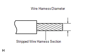
Wire harness: Stripped wire harness section 1.25 mm2 or more (0.00193 in.2 or more) CAUTION: If the wire harness is too thin or an alternative object is used to tie down the curtain shield airbag, it may be snapped by the shock when the airbag is deployed. Always use a wire harness for vehicle use with an area of at least 1.25 mm2 (0.00193 in.2). HINT: To calculate the area of the stripped wire harness section: Area = 3.14 x (Diameter)2 divided by 4
(2) Tie the curtain shield airbag to the tire with several wire harnesses. CAUTION: Make sure that the wire harnesses are tight. If there is slack in the wire harnesses, the curtain shield airbag may become loose due to the shock when the airbag is deployed. NOTICE: As the tires may be damaged by the airbag deployment, use a tire that you are planning to throw away. (e) Install SST. (1) After connecting SST each other, connect them to the curtain shield airbag. SST: 09082-00802 09082-10801 09082-40800 (f) Place the tires. 
NOTICE: Do not place the deployment direction of the curtain shield airbag facing the ground. (1) Place at least 2 tires under the tire which the curtain shield airbag is tied to.
(h) Deploy the airbag. (1) Connect the red clip of SST to the battery positive (+) terminal and the black clip of SST to the battery negative (-) terminal. (2) Check that no one is within a 10 m (32.8 ft.) radius of the tire which the curtain shield airbag is tied to. (3) Press SST activation switch and deploy the airbag. CAUTION: When deploying the airbag, make sure that no one is near the tire. HINT: The airbag is deployed as the LED of SST activation switch comes on.
|
Toyota Tundra Service Manual > Power Window Control System(w/ Jam Protection Function): Operation Check
OPERATION CHECK 1. CHECK WINDOW LOCK SWITCH (a) Check that the front passenger side power window and rear power windows cannot be operated when the window lock switch of the master switch is pressed. OK: Operation of front passenger side power window and rear power windows is disabled. (b) Check tha ...