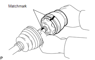
DISASSEMBLY PROCEDURE 1. REMOVE INBOARD JOINT BOOT CLAMP (a) Using a side cutter, cut the 2 inboard joint boot clamps and remove them. 2. DISCONNECT INBOARD JOINT BOOT (a) Disconnect the inboard joint boot from the inboard joint shaft. 3. REMOVE INBOARD JOINT SHAFT
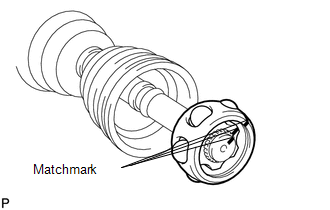
(b) Using a screwdriver, remove the snap ring from the outboard joint shaft. (c) Remove the inboard joint shaft from the outboard joint shaft.
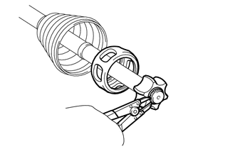
(e) Remove the 6 balls. (f) Slide the cage to the outboard joint side.
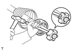
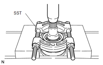
(i) Remove the cage. 4. REMOVE INBOARD JOINT BOOT (a) Remove the inboard joint boot from the outboard joint shaft. 5. REMOVE OUTBOARD JOINT BOOT CLAMP (a) Using a side cutter, cut the 2 outboard joint boot clamps and remove them. 6. REMOVE OUTBOARD JOINT BOOT (a) Remove the outboard joint boot from the outboard joint shaft. 7. REMOVE FRONT DRIVE SHAFT DUST COVER LH
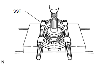
8. REMOVE DUST SEAL
|
Toyota Tundra Service Manual > Dynamic Radar Cruise Control System: Freeze Frame Data
FREEZE FRAME DATA CHECK FREEZE FRAME DATA HINT: The ECU records vehicle and driving condition information as freeze frame data the moment a DTC is stored. (a) Connect the Techstream to the DLC3. (b) Turn the ignition switch to ON. (c) Turn the Techstream on. (d) Enter the following menus: Powertrain ...