DESCRIPTION The main body ECU (multiplex network body ECU) receives seat memory switch signals from the outer mirror control ECU assembly via CAN communication. If the seat memory SET switch is being pressed when one of the M1or M2 switches is pressed, or if either of the M1 or M2 switches is pressed within 3 seconds of pressing the seat memory SET switch, the main body ECU (multiplex network body ECU) sends a memory request signal to the position control ECU and switch assembly. After receiving the request signal, the position control ECU and switch assembly memorizes the location data of each motor. WIRING DIAGRAM 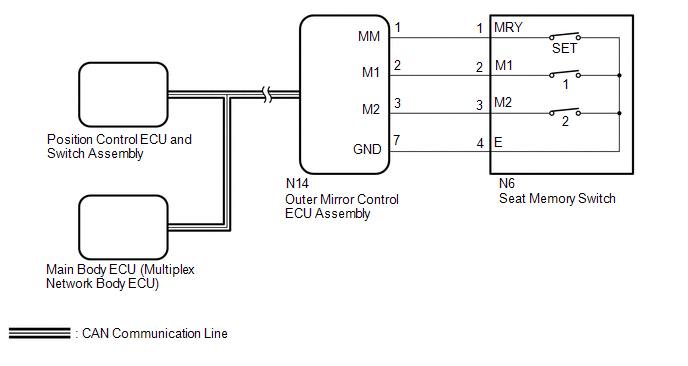
PROCEDURE
(a) Use the Techstream to check if the CAN communication system is functioning
normally (See page OK: CAN communication DTC is not output.
(a) Check that each function of the power seat operates normally by using the
power seat switches (See page OK: Each function of the power seat operates normally by using the power seat switches.
(a) Connect the Techstream to the DLC3. (b) Turn the ignition switch to ON. (c) Turn the Techstream on. (d) Enter the following menus: Body Electrical / Driver Seat / Data List. (e) Read the Data List according to the display on the Techstream. Driver Seat
OK: ON or OFF is displayed on the Techstream according to the table above.
(a) Connect the Techstream to the DLC3. (b) Turn the ignition switch to ON. (c) Turn the Techstream on. (d) Enter the following menus: Body Electrical / Driver Seat / Active Test. (e) Perform the Active Test according to the display on the Techstream. Driver Seat
OK: Buzzer sounds normally.
(a) Temporarily replace the outer mirror ECU assembly with a new or normally
functioning one (See page
(a) Perform a memory operation and check that the buzzer sounds to indicate the
completion of the memory operation (See page NOTICE:
OK: Seat position memory function operates normally.
(a) Temporarily replace the position control ECU and switch assembly with a new
or normally functioning one (See page
(a) Perform a memory operation and check that the buzzer sounds to indicate the
completion of the memory operation (See page NOTICE:
OK: Seat position memory function operates normally.
(a) Remove the seat memory switch (See page (b) Inspect the seat memory switch (See page
(a) Disconnect the N14 outer mirror control ECU assembly connector. (b) Disconnect the N6 seat memory switch connector. (c) Measure the resistance according to the value(s) in the table below. Standard Resistance:
|
Toyota Tundra Owners Manual > Instrument cluster: Fuel consumption
information
The fuel consumption information can be displayed on Entune Audio, Entune Premium Audio and Entune Audio Plus screen. Display the trip information or past record screen Entune Audio Press the "TRUCK" button. Entune Premium Audio and Entune Audio Plus Press the "APPS" button, and then select "Eco" o ...

 ).
).


