DESCRIPTION
WIRING DIAGRAM 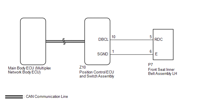
PROCEDURE
(a) Use the Techstream to check if the CAN communication system is functioning
normally (See page OK: CAN communication DTC is not output.
(a) Check that each function of the power seat operates normally by using the
front power seat switches (See page OK: Each function of power seat operates normally by using the front power seat seat switches. Result
(a) Perform a memory operation and check that the buzzer sounds to indicate the
completion of the memory operation (See page NOTICE:
OK: Seat position memory function operates normally.
(a) Connect the Techstream to the DLC3. (b) Turn the ignition switch to ON. (c) Turn the Techstream on. (d) Enter the following menus: Body Electrical / Driver Seat / Data List. (e) Read the Data List according to the display on the Techstream. Driver Seat
OK: "ON" and "OFF" appears on the screen.
(a) Temporarily replace the position control ECU and switch assembly with a new
or normally functioning one (See page
(a) Check that the power seat easy access system operates normally when engaging
and disengaging the tongue plate of the front seat inner belt with the shift lever
in P (See page OK: Power seat power easy access system is normal.
(a) Remove the front seat inner belt assembly LH (See page
(b) Inspect the front seat inner belt assembly LH (See page
(a) Disconnect the Z10 position control ECU and switch assembly connector. (b) Disconnect the P7 front seat inner belt assembly LH connector. (c) Measure the resistance according to the value(s) in the table below. Standard Resistance:
|
Toyota Tundra Service Manual > Rear Axle Shaft: Installation
INSTALLATION PROCEDURE 1. INSTALL REAR AXLE SHAFT OIL SEAL (a) Using SST and a hammer, tap in a new oil seal. SST: 09950-60020 09951-00770 SST: 09950-70010 09951-07150 (b) Apply MP grease to the lip of the oil seal. NOTICE: Do not allow foreign matter, etc. to contact the axle shaft housing hole. 2. ...

 ).
).


